Related Projects: Nitrous Model, Nitrous Run Valve, Nitrous Tank (2022/23), Nitrous Feed
Role: Responsible Engineer, Scope Owner
Duration: September 2023 – May 2024
Requirements: Develop a lightweight Nitrous Oxide bolted closure pressure vessel that interfaces with the Nitrous feed system.
Summary:
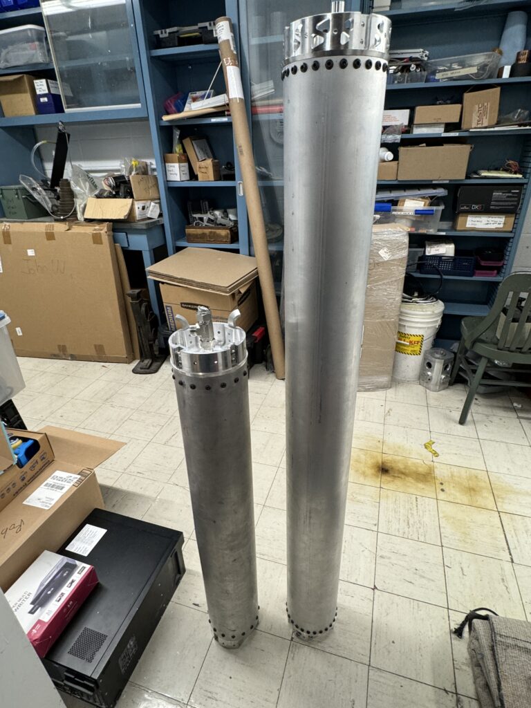
The 2024 Nitrous tank is a substantial iterative improvement on the 2023 Nitrous tank. There were several key areas that I thought could be improved:
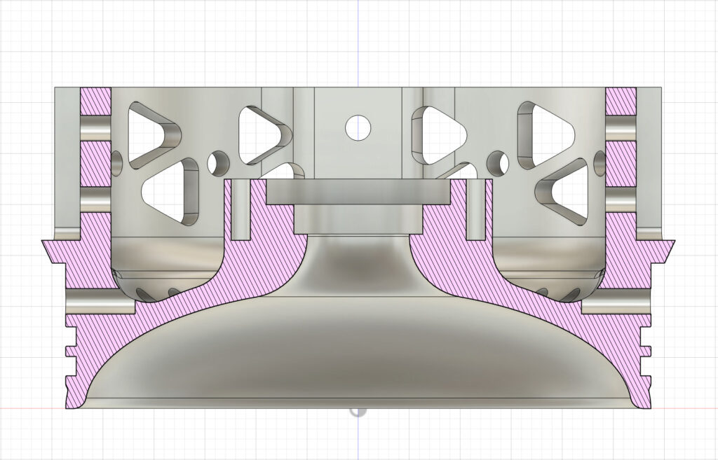
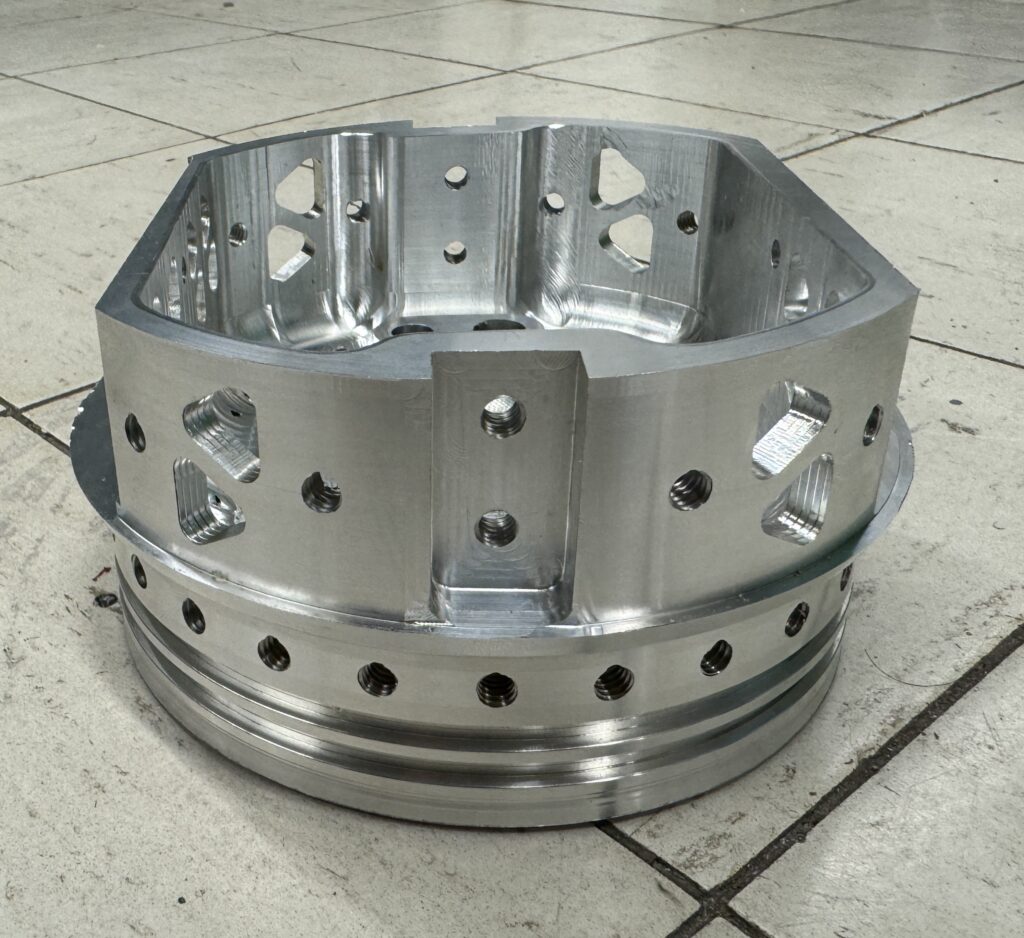
- Mass: Traded adding additional bolts for a lower wall thickness, reducing the wall from 0.1875 in to 0.125 in and increasing the number of bolts to 28.
- Ellipsoidal End Caps: Although hemispherical end caps are the best for stress distribution, ellipsoidal end caps are lighter overall because of the manufacturing method.
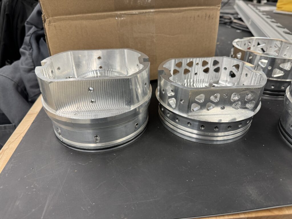
- Lightweighting: Performed additional finite element analysis to remove mass in high margin areas.
For the design parameters, I used our internal pressure vessel design spreadsheet that solves for hoop stress, bearing stress, bolt tear-out stress, and casing tensile stress, which were the constraining forces.

To size the tank, I used our target oxidizer mass (30.6 lbs), added some margin in case our performance parameters increase during the testing campaign after consulting with our thrust chamber team (35 lbs), then used the maximum temperature (and minimum density) our nitrous oxide would experience (850 psi, 6.066 lbs/gal) [obtained using REFPROP] to size the tank.
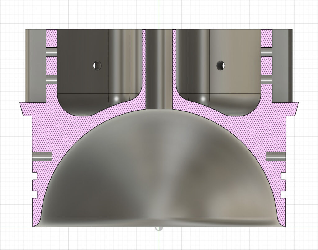
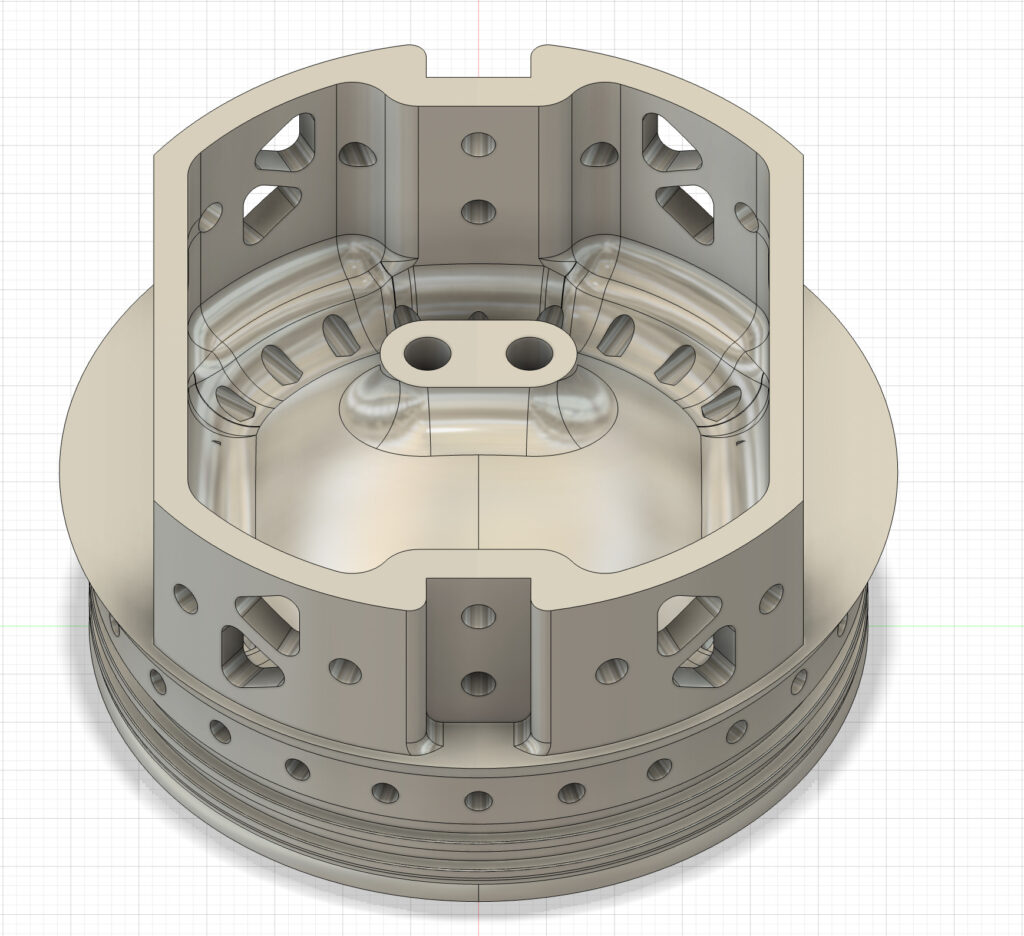
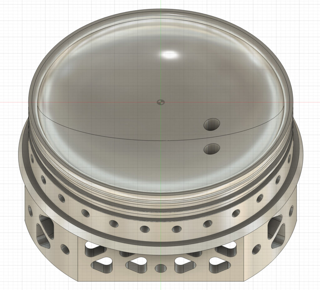
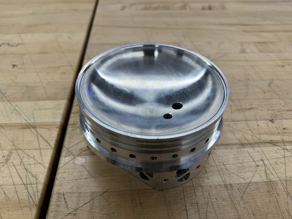
The Nitrous also now filled through a separate radially offset NPT fitting. I also added an additional port for a pressure transducer on the bottom end cap. This serves several purposes:
- Provides redundant tank pressure data ( + pgh of filled nitrous oxide which can fluctuate based on mass and temperature but is on the order of .75 psi).
- Provides a direct pressure drop across the pneumatic valve (we also have a transducer at the injector manifold).
- Also allows us to observe any changes in the compressibility effects.
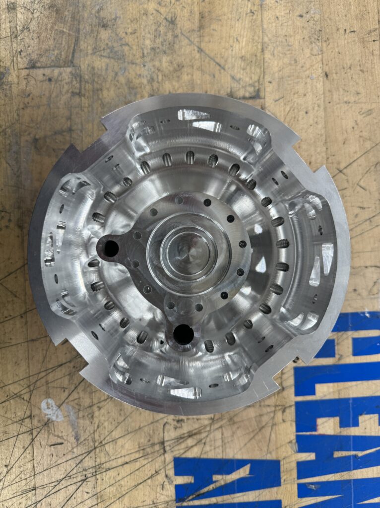
The bottom-end cap design is shown below:
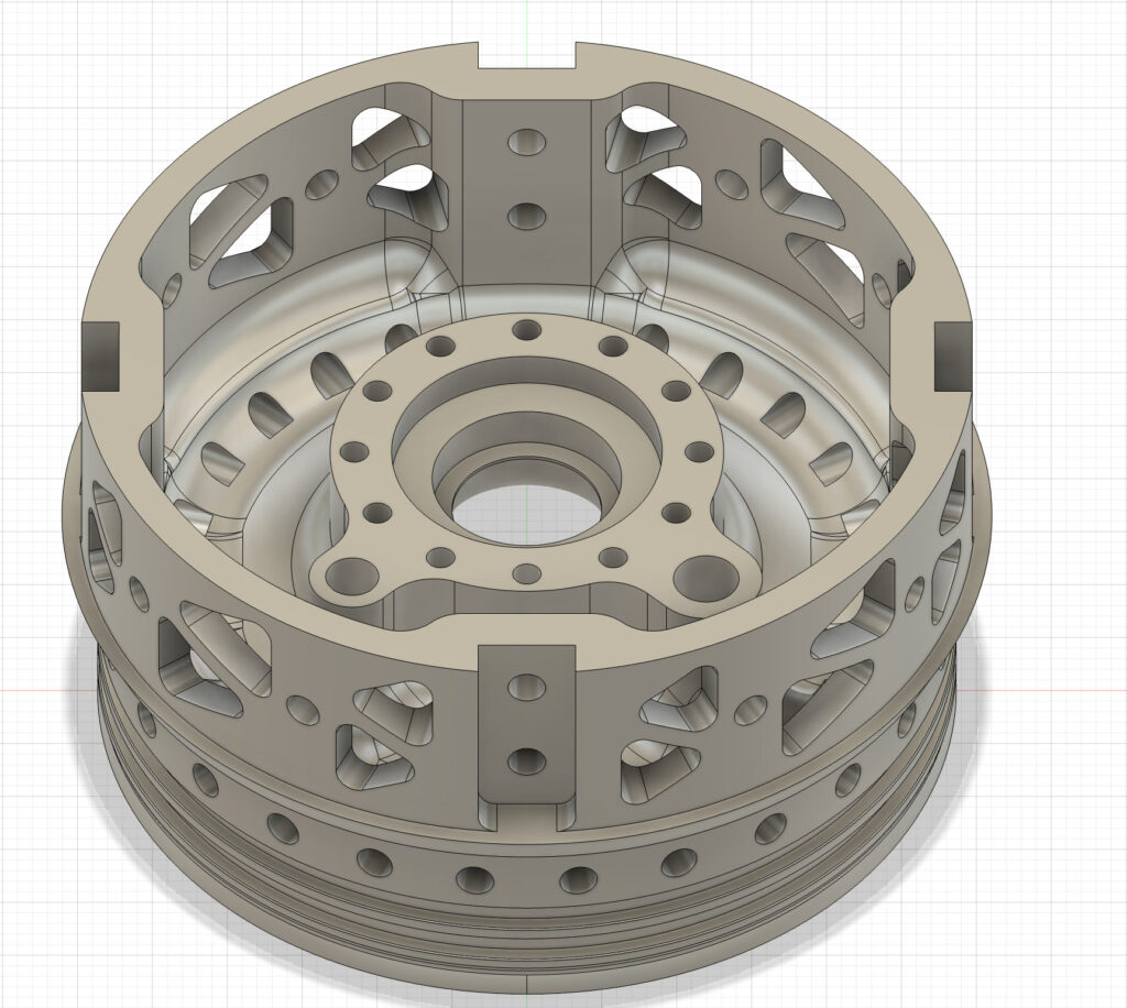
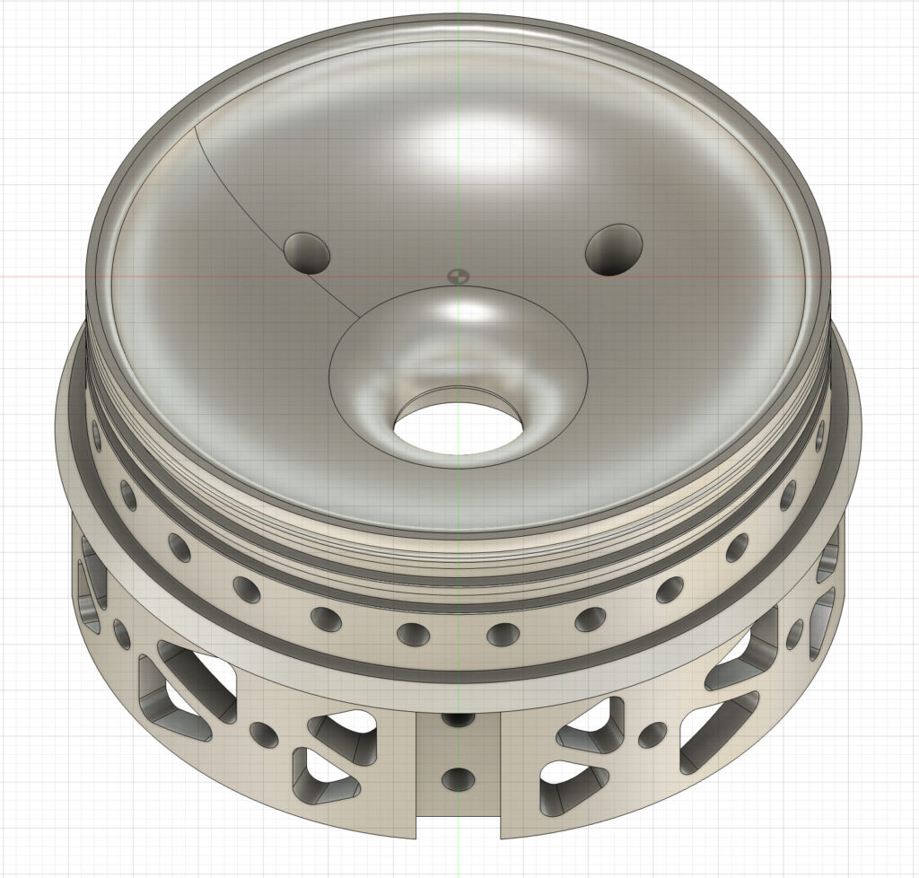
The top end cap was modified to be easier to assembly. With the bulkhead interface, it was difficult to tighten fittings and sensors. Offsetting the ports makes it easy to fit a wrench inside.
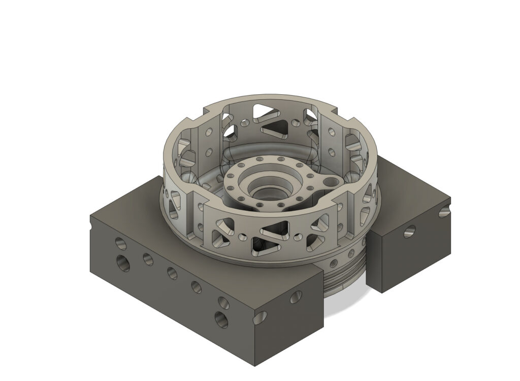
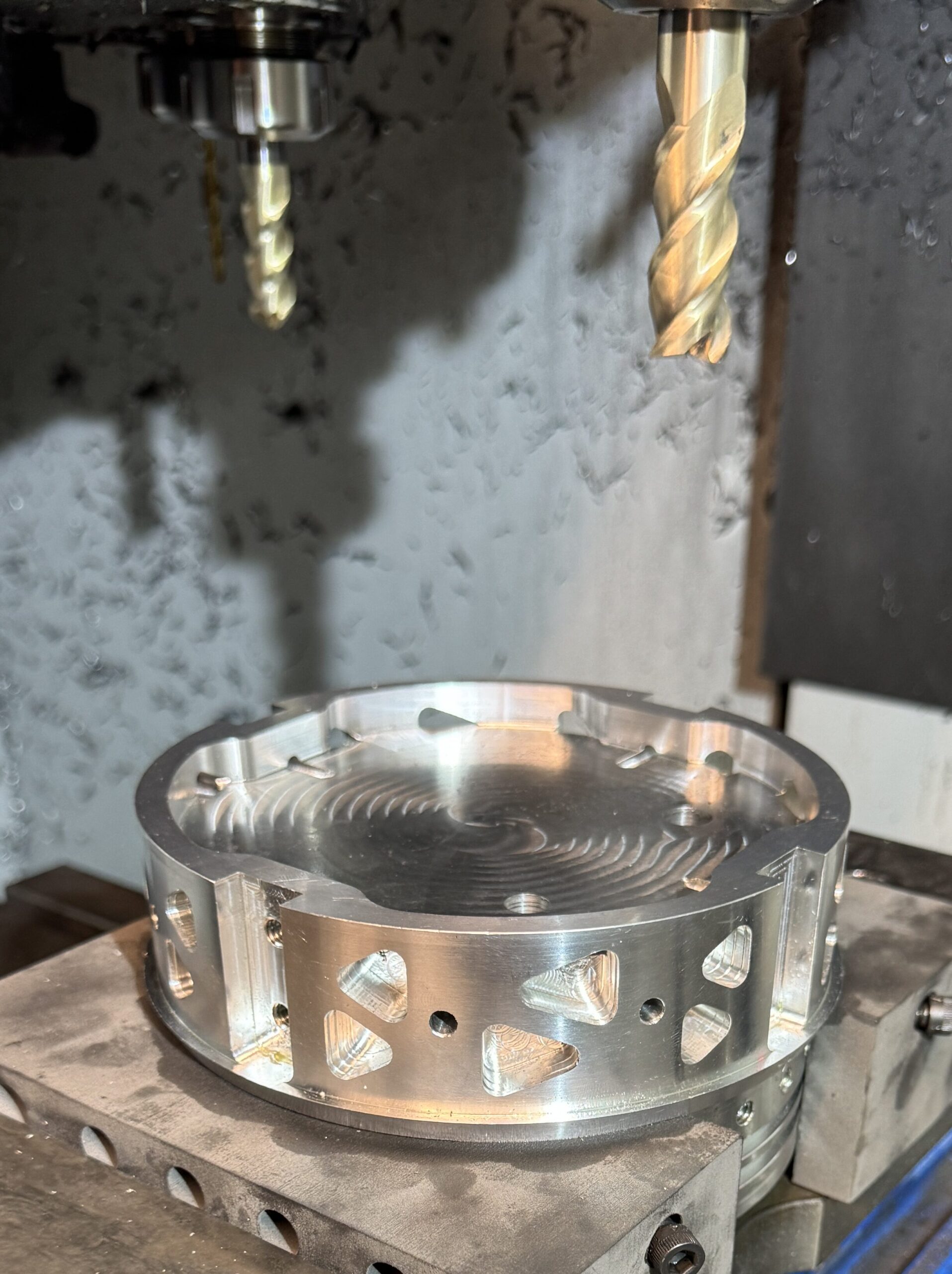
I programmed these parts to be machined on our Haas ST-20Y 4-axis CNC lathe. A sped-up video of the CAM of these components is shown below:
The tooling was Nylon 12 SLS printed and exceedingly strong. The CAM for the bottom end cap was very similar to that of the top end cap.
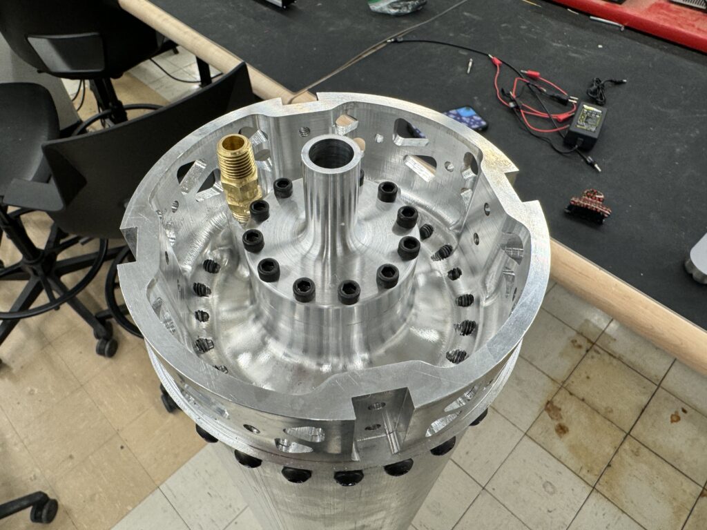
I switched from 70D to 90D 254 o-rings for sealing between the end cap and the ox tank tube. The main benefit of this change is improved resilience during installation and higher resistance to extrusion during testing.

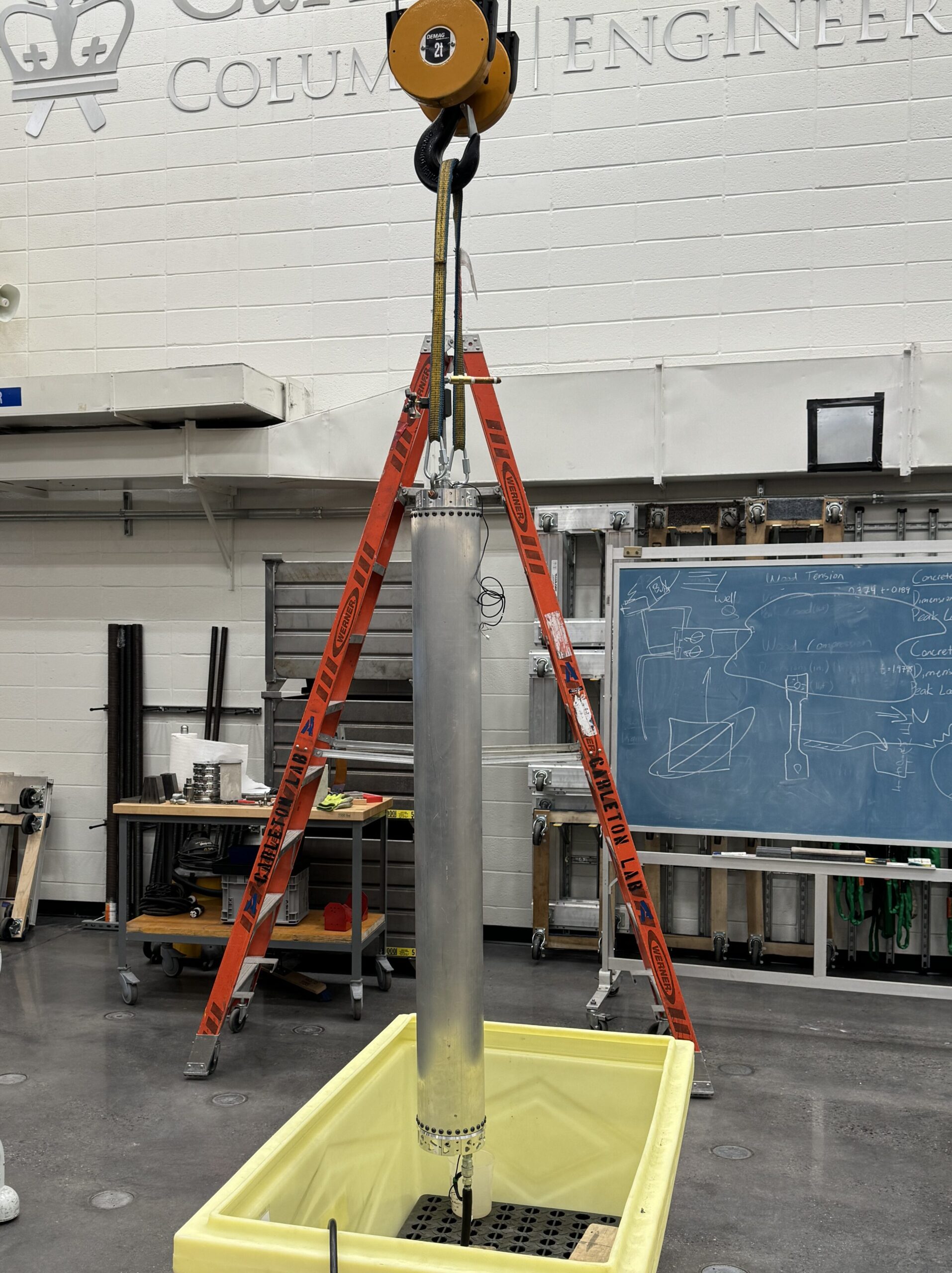
It was hydrostatically proof testing to 1.5x MEOP (1050 psi) for 30 minutes.