Summary: I set a personal goal to certify NAR L1 and L2 during the summer of 2023. After scratch-building a high-powered rocket with a modular motor interface, I accomplished my goal and earned the certifications.
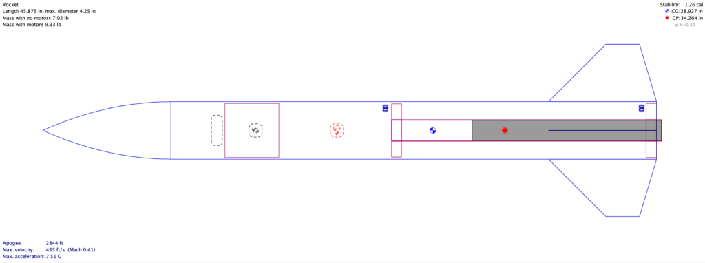
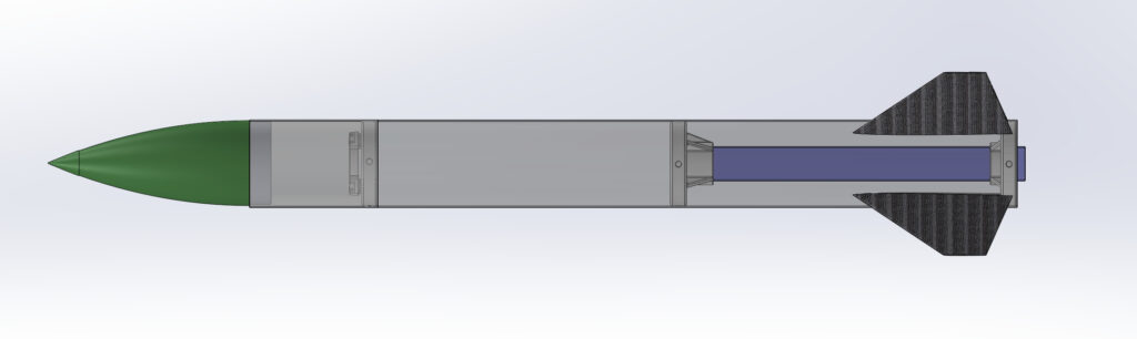
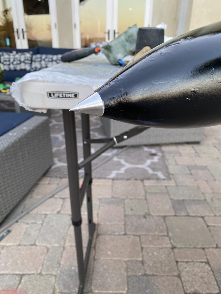
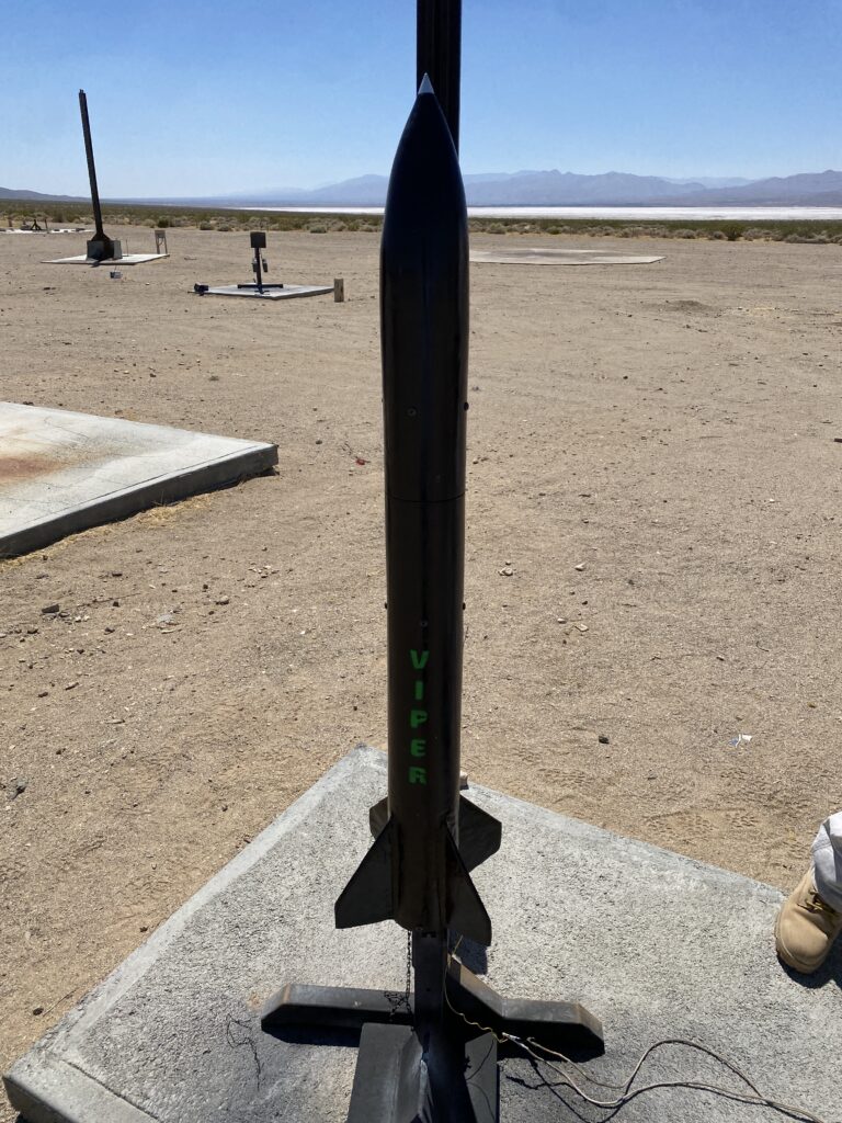
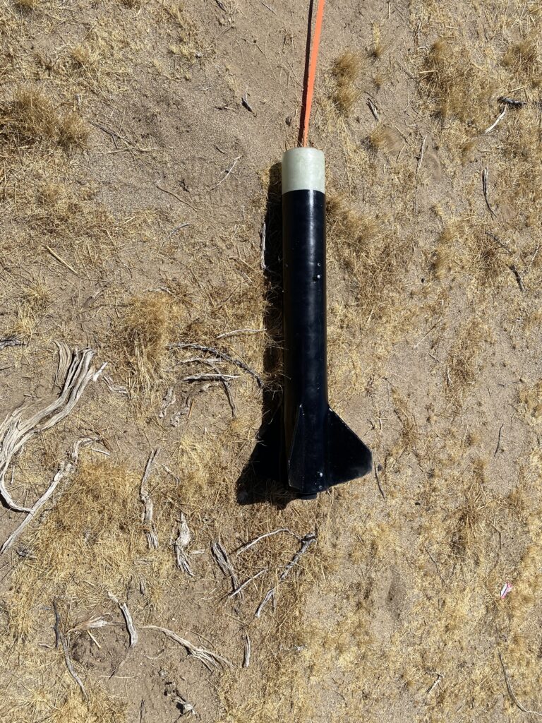
Article: I decided to build the same rocket for my L1 and L2 certification flights. Viper is a 4.25″ OD, 4″ ID rocket with 4 trapezoidal NACA 0015 fins, a 9.5″ parabolic nosecone, and a 38mm motor tube. It uses a 48″ parachute with a Cd of 1.5, landing at 19 fps, and should have an apogee of 905 feet on the L1 flight and 2,846 feet on the L2 flight.
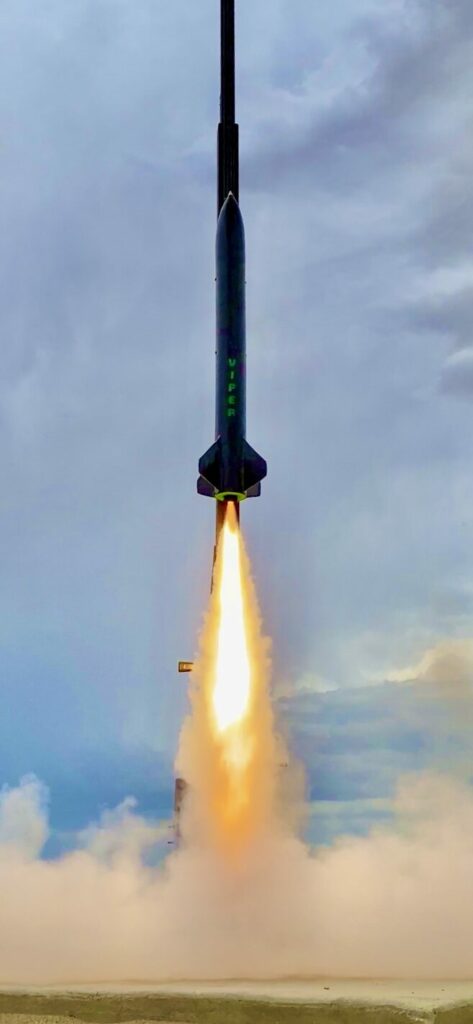
Viper was launched at FAR (Friends of Amateur Rocketry) in the Mojave Desert on August 5th, 2023 off of a 10-foot rail. It launched again on August 19th, 2023, off a 20-foot rail for my L2 certification. It uses redundant electronic and motor ejection systems to ensure recovery success and has a single main parachute.
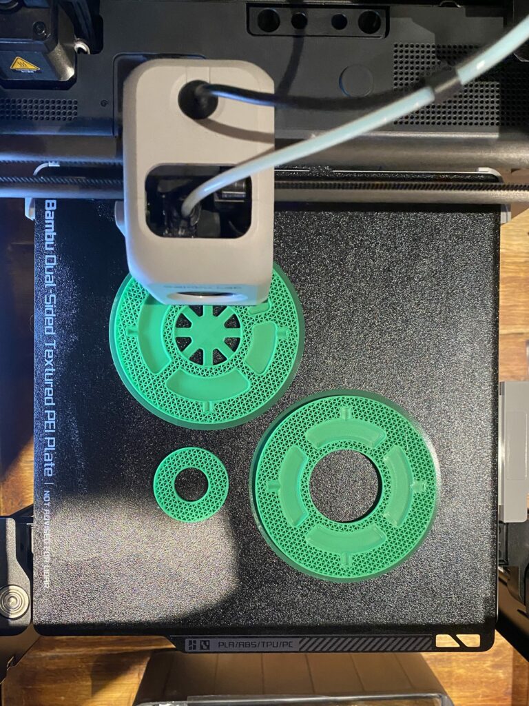
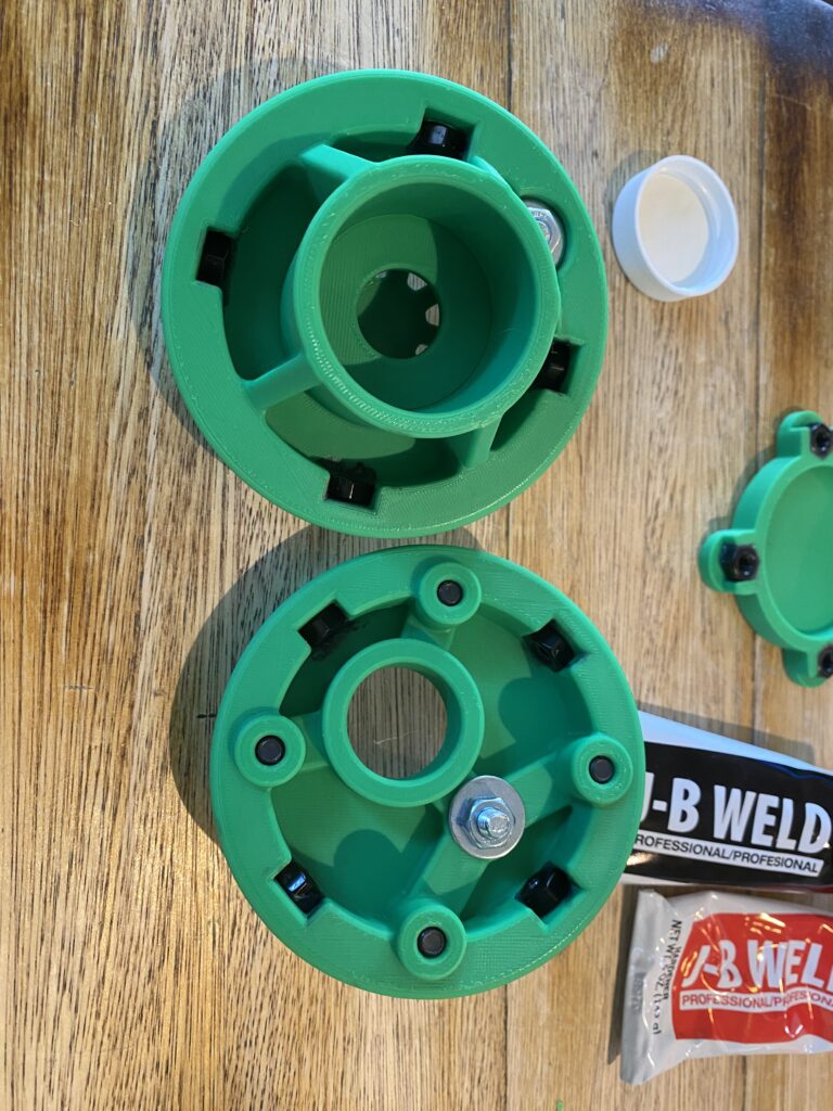
Viper is constructed of two materials: fiberglass and 3D-printed ABS. I originally used PLA to 3D print the motor centering rings, recovery bulkhead, tracker stand, and fin/nosecone molds. However, after some tests, I became concerned with PLA’s poor heat tolerance. Considering the Mojave can often exceed 110 degrees ambient, I decided to reprint the centering rings and recovery bulkhead from ABS, which is less rigid but has excellent heat tolerance.
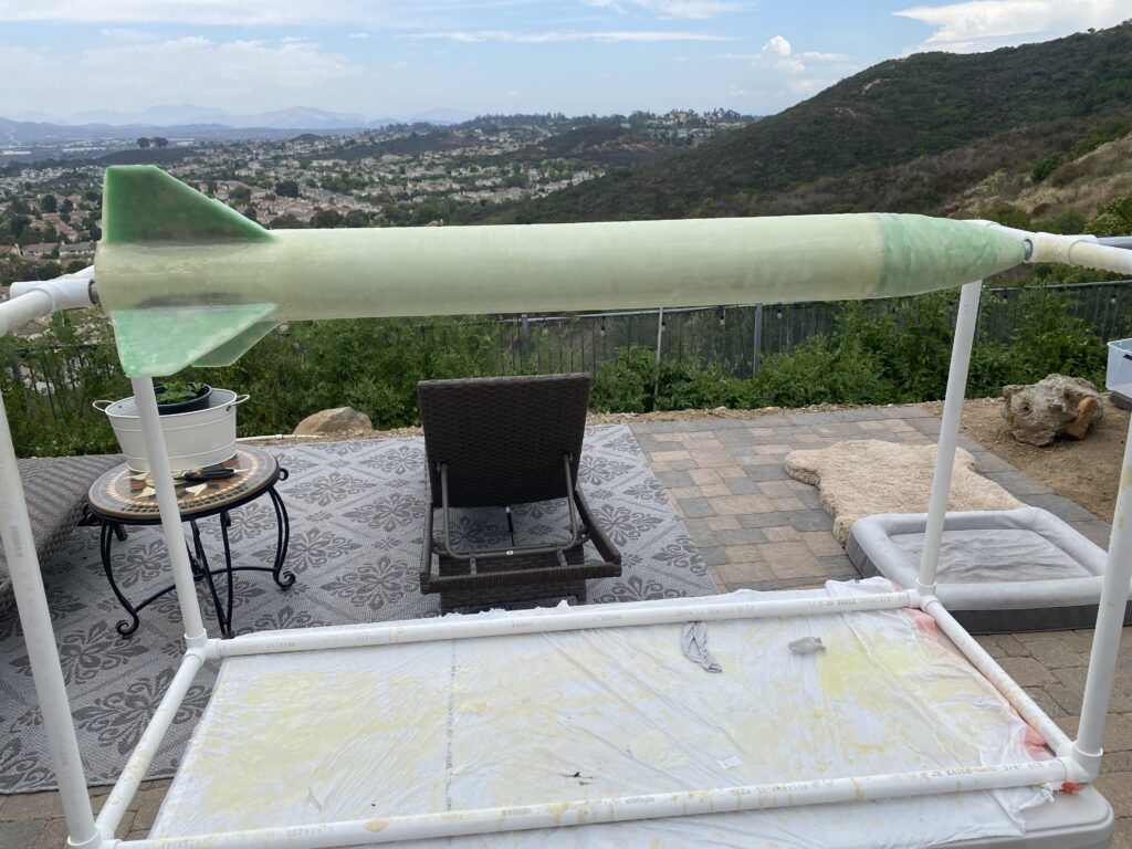
For the body tube, nosecone, and fins I laid a single piece of fiberglass. While this means compromising on modularity for future upgrades of Viper, I made this decision to ensure that the entire vehicle was completely rigid, especially since the fins were surface mounted.
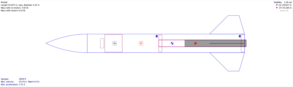
The first step was designing the vehicle in Open Rocket. Since it needs to be stable for both I and J motors, I had to consider both options in the simulations. I also wanted the vehicle to be stable at supersonic speeds for future proofing.
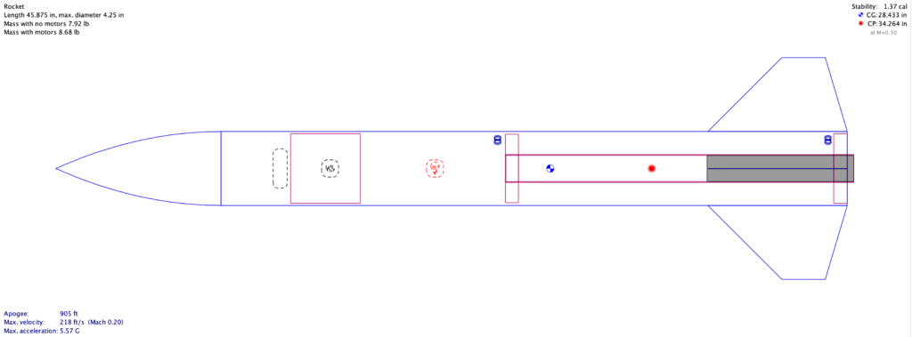
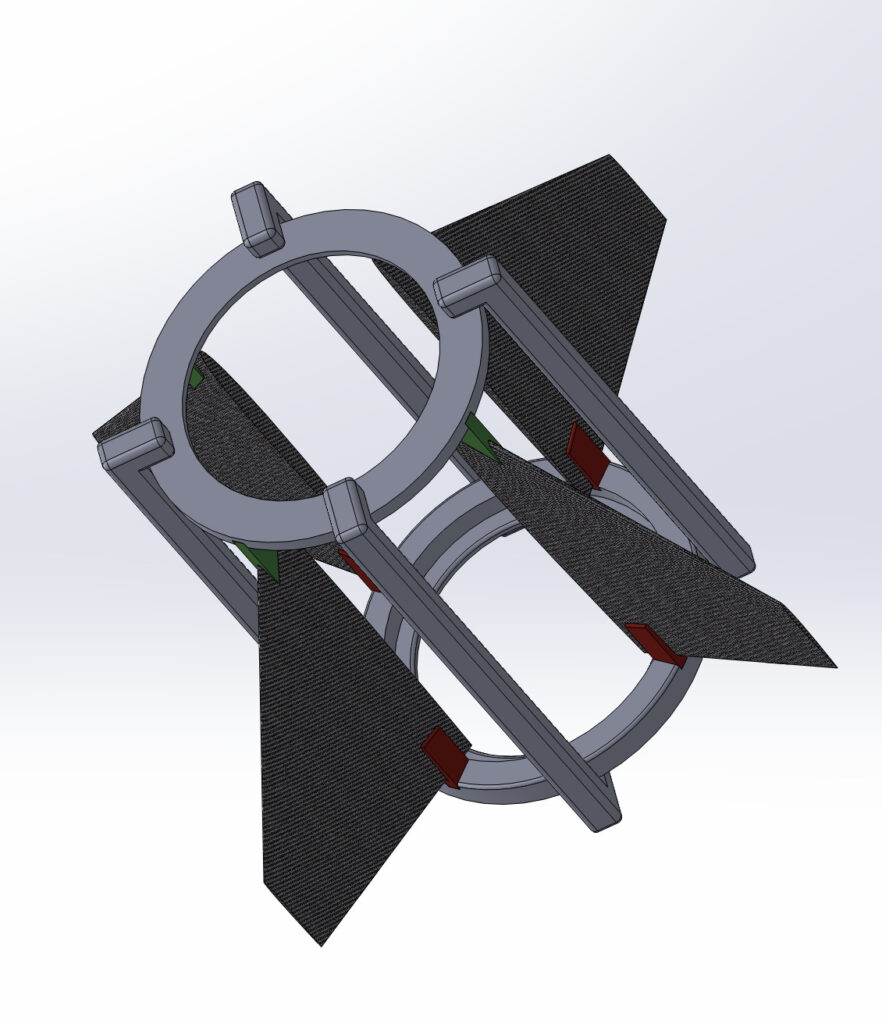
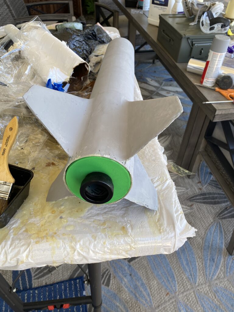
The fins are trapezoidal, with a root chord of 8″, tip chord of 2.5″, height of 4.25″, and sweep of 45 degrees. They are based on a NACA 0015 airfoil and taper along its chord. Since this project was my first time laying up fins in fiberglass, I didn’t want to overcomplicate the design, so I stuck with a strong and simple airfoil that would reduce drag.
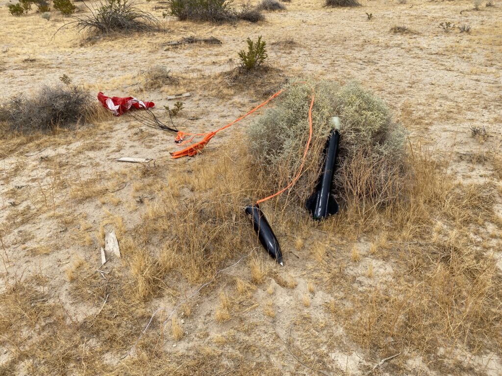
Fin flutter onset would begin at 1,628 mph (Mach 2.12) so the fins would be more than strong enough for any conceivable flight. Furthermore, the fins would be sturdy so that, during recovery, they wouldn’t snap upon impact with the ground (where damage upon recovery would invalidate the certification flight).
I used steel nuts for the motor centering rings to allow for repeated installation cycles. The motor tube is modular and allows for swapping between 38mm and 54mm sizes.
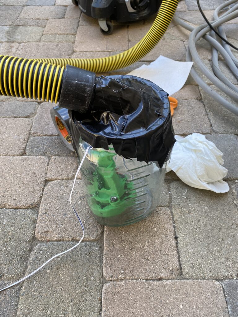
I also designed a gas baffle to prevent hot ejection gases (generated by the black powder charge) from burning through the parachute.
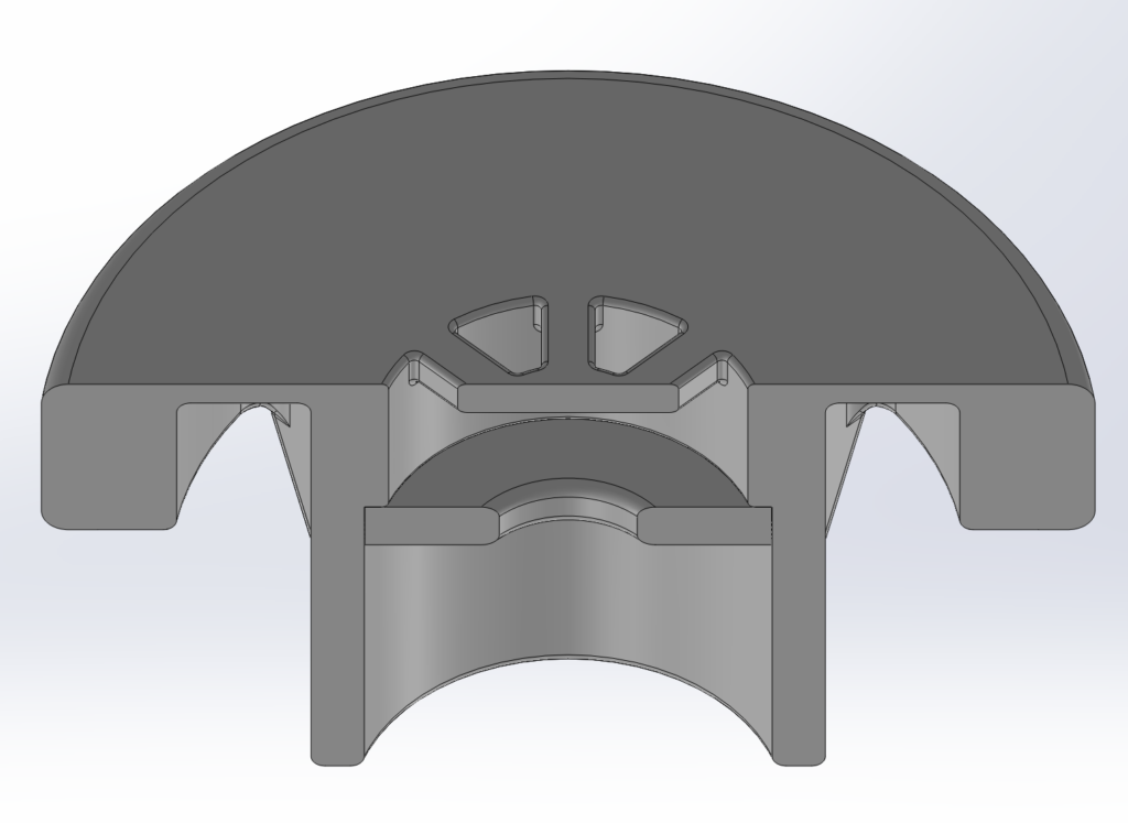

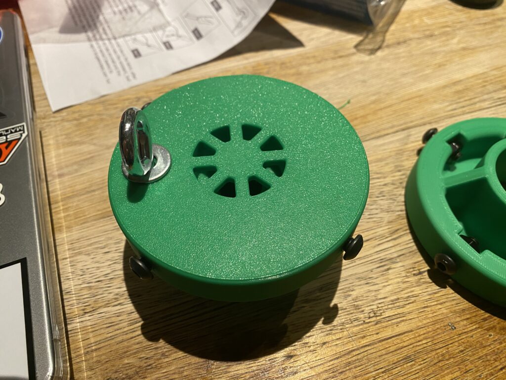
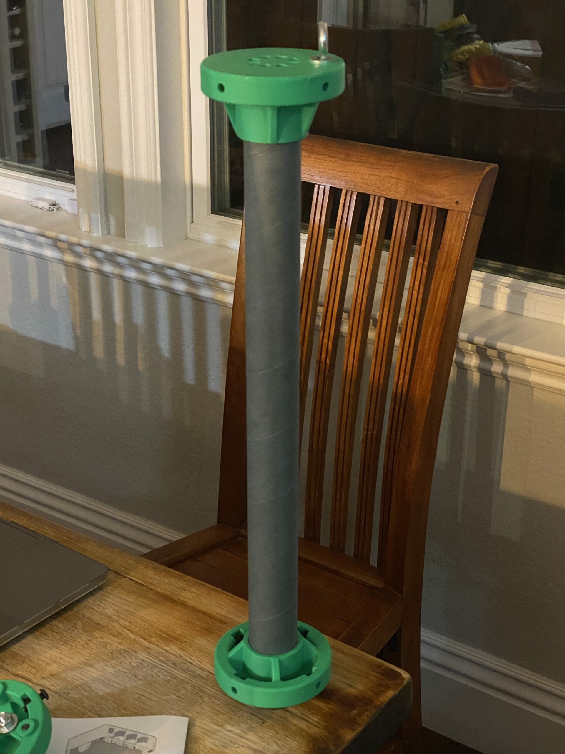
The motor tube interfaces with the airframe using 4 1/4-20 bolts. I epoxied nuts in the slots in the centering rings for securing the bolts. Based on my shear calculations, the factor of safety of 1/4-20 bolts in 1/8″ thick fiberglass was 3x greater than even the forces sustained under a K motor, so I was confident this solution would be strong enough.
For the fiberglass layups, I decided to use 6oz fiberglass cloth with epoxy resin from Total Boat. I used 8 layers of fiberglass on all surfaces. One mistake I made was not using the established nosecone manufacturing method of laying up the fiberglass cloth in a clamshell-like mold.
Recovery used a 48″ elliptical parachute and 30ft tubular nylon shock cord. I also manufactured a fiberglass coupler tube that fits between the two halves.
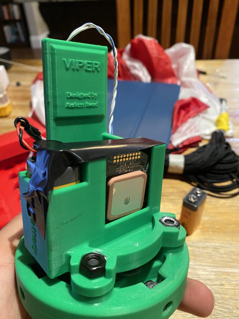
To achieve my objectives of L1 and L2 certification for the summer, I had two weeks of turnaround to prepare for the L2 flight after my L1 cert. Other than preparing for the exam, I also wanted to include redundant electronic recovery deployment.
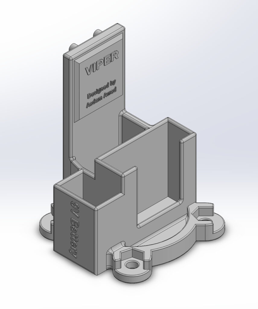
I purchased a standard dual deployment altimeter, a Missileworks RRC3, that I could grow into with future projects (it then happened to fly on our hybrid rocket at FAR-OUT as a deployment altimeter). I also decided to strip down a commercial car GPS tracker.

For the electronic deployment I only wired up the e-match to the drogue terminal. In a dual-deployment setup, the drogue parachute should be fired at apogee. Then, once the barometer detects the vehicle has reached some pre-programmed altitude, the main parachute will deploy. Since Viper is only designed to use a single main parachute, only the drogue terminal is needed.
Once all the new hardware was fully tested, I prepared the vehicle for flight. After getting 40/40 on the L2 exam, it was time to fly.

Throughout the process of building and flying Viper, I learned about composites, rocketry principles, electronics, solid rocket motors, and aerodynamics. I’ve since focused on fluids and components engineering, but the foundation I gained in rocketry principles through this project has been invaluable.