Related Projects: Nitrous Tank (23/24), Nitrous Feed
Role: Responsible Engineer, Scope Owner
Requirements: Develop a run valve for Nitrous Oxide. It needs to be manufacturable on a 4-axis CNC lathe, use common machinable alloys, actuated in < 20 ms using Nitrous vapor as a working fluid, and compact.
Summary:
For the 23-24 rocket development cycle, I led our team in designing, machining, qualifying, and testing a coaxial pneumatic valve. It powered a 1200 lbf hybrid rocket motor, generating 16Gs of acceleration and recovering successfully in June 2024.
The Nitrous run valve is a pressure-assisted design, with a MEOP of 900 psi and proof of 1,350 psi. It is sealed with 25% glass-filled PTFE, has a 1″ diameter orifice, and has both single and double-acting modes. The valve body is machined from 6061-T6 aluminum. It uses Nitrous vapor as the muscle gas.
There were several reasons for developing a custom valve:
- Overall system mass: 316 SS ball valve + 125 kg/cm servo, housing, and linkage added dry mass to the fluids system. A custom aluminum valve decreased overall system mass.
- Head Loss: The Swagelok 3/4″ ball valve we used in the 2022/23 rocketry design cycle had an orifice diameter of 0.4″. This had a calculated headloss of 49.21 psi, which has a performance penalty.
- Actuation Time: Ball valves with electric actuators have a trade between actuation time and actuator size.
A coaxial design was chosen because it is manufacturable, compact, and proven.
I authored this document explaining all of the calculations used to size the pneumatic valve. It uses a deprecated design with compressed air for actuation. The same modeling was done for the LOX Run Valve.
Code used to simulate valve actuation:
Based on all of these parameters, I finalized the dimensions and allocated CAD to our subteam members. I instructed them in using the Parker ORD handbook for GD&T of o-ring grooves (dynamic & static), proper CAD modeling techniques in Fusion 360, and FEA of components to generate a suitable factor of safety. I modeled any remaining components myself, then instructed our team in computer-aided machining (CAM).
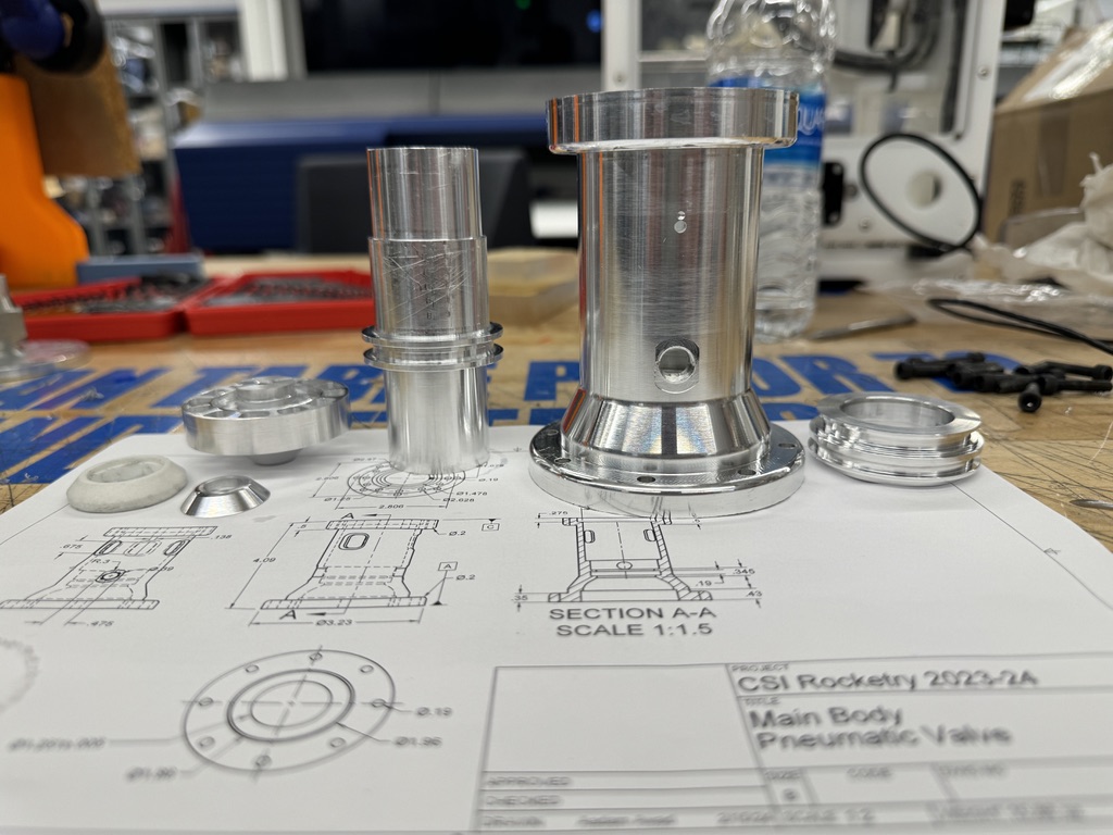
I created this drawing packet summarizing each in-house component.
Machining the pneumatic valve was a joint effort. Due to tolerance stack-ups in the manufacturing process, we scrapped some components or modified them.
After completing valve machining, several iterations of the PTFE seal geometry were required. Initial hydrostatic testing showed significant leakage through the PTFE seal, indicating the piston was not compressing the PTFE sufficiently.
After three PTFE seal iterations, the leak path was identified as being a coaxial tolerance stack-up in the seal seat design. I designed the seal seat outer lip to be the same diameter as the piston erroneously. This meant that any loss in concentricity would lead to a part of the piston contacting aluminum, rather than PTFE, and sealing insufficiently. The fix for this was re-machining the PTFE ring with a raised inside lip, which contacted the piston first. This worked exceptionally well and there have been no sealing problems since.

The coaxial pneumatic valve enabled as-designed oxidizer mass flow rates to the 1200lbf Valkyrie 2 hybrid rocket motor. The increased combustion chamber temperatures and pressures led to a burn-through and required redesigning the phenolic insulation.
Another benefit of the coaxial pneumatic valve was a significant reduction in fluid interstage length:


A:B of valve configurations.
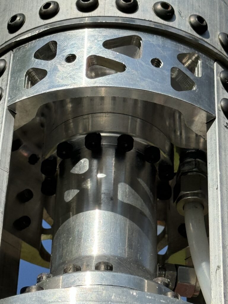
The coaxial pneumatic valve powered our hybrid rocket engine at the inaugural FAR-OUT competition in June 2024.